In this entry, we’ll discuss equations and variables. By using variables, you can assign a
dimension to multiple features or sketches and update them from one
location. This is much easier than
trying to remember in your model where the dimension 15mm occurs. Also, an equation in SOLIDWORKS is a very
powerful tool. You can control parts and
have them automatically update in regards to new dimensions or updated
dimensions in a design.
Segment 1 uses variables and equations throughout the
test. Before we begin the exam, let’s
turn on two features in SW that will come in handy. If we go to Tools/Options – System Options
then Feature Manager, we can set Equations and Sensors to ‘Show’. This will populate both in the design tree so
we can easily find it when we are working on our test. We will discuss Sensors later in the blog.
Now when we start a new part, in the feature tree, we can
see both of these options.
When we start our test, we see that we are given some
variables and further into the test, we are given an equation. Let’s look at how to enter these variables
and equations before we even start modeling.
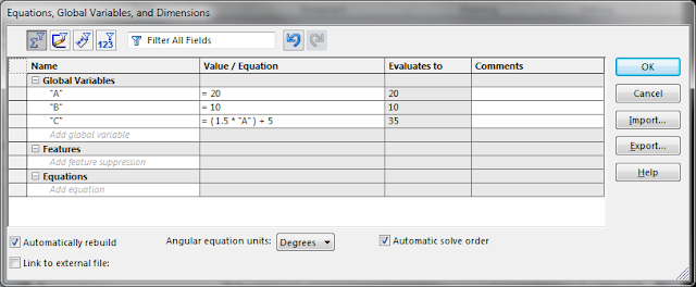
We will start a new part, right click on the equations
folder and select ‘Manage Equations’. This
will open up our equations dialog box.
Under Global Variables, type the letter A. Tab over to Value/Equation
and give it a value of 20. Hit the Enter
Key and it takes you to the comments box.
In a real world application, you can give this variable a description so
that people after you know what it is.
For the purpose of the test, there isn’t much value in this field. If you hit Enter again, it drops you to a new
line under “A”. Now set B equal to 10
and start a third line. On the third
line, we are going to set C equal to the equation (1.5*’A’)+5. You will notice at the bottom of the equation
manager that there is an equation section.
This is for a direct application of an equation to a dimension. While it is not needed for the exam, you can
double click a dimension and apply an equation to it from directly in the
model. The equation will be displayed
here. Let’s also check the ‘Automatically
Rebuild” box. We can now click OK and
close out the equation manager dialog box.
Let’s start our part on the top plane. Select this plane and start a sketch. On this plane, we will sketch two circles
with the center on the origin, one slightly bigger than the other. Put a dimension on both, the value does not
matter at this point.
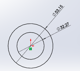
Double click the dimension for the inner circle (32.27
above). If we type =A in the dimension,
we can now link this dimension to the variable A.
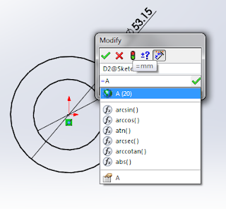
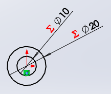
Click the check and repeat the process for the second
dimension, linking it to B.
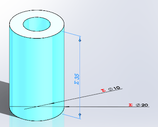
You will see that we now have our diameters linked to our
variables and SOLIDWORKS is show us a new symbol (Red Sigma) that means we are
linked to the equations manager.
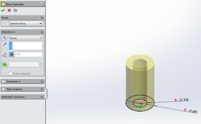
Now, let’s extrude this part. Select the Features tab, click Extrude
Boss/Base and in the Direction one boss, set D1 equal to C. Click the check mark and we have a part!
Why is this important?
On the exam, the variable will change.
The variables are also used multiple times in the exam. This is done to force you to show your
knowledge of how to use them. It’s much
easier to change A in the Equation Manager rather than sift through your models
and find every instance of A.
If we open the equations manager again by right
clicking on equations and selecting manage equations we can change these
variables. Let’s change A from 20 to
30. Move the equations manager off the
model so you can see what happens when you click ok.
Our part changed from this:
To This:

Diameter A updated from 20 to 30 and Length C updated to
from 30 to 50.
If you have any questions on equations, post them below and
we will discuss them.
Next time we’ll talk about materials and mass.
Bryan


