We will start our next topic, the CSWA, in a couple of weeks.
I'm going to take some time off in order to attend an event in Boston to see what SOLIDWORKS 2016 is going to look like.
I'll be tweeting and blogging on the new version of our favorite software from the certification point of view.
If you have any questions, post them here or hit me up at my twitter account SWCertGuy.
Enjoy!
Bryan

Tuesday, September 8, 2015

CSWP, Segment 3: Replace Component
 SOLIDWORKS also makes it very easy to replace one component with another. Let's work with the assembly we have used in the last couple of posts Here. Also download the Updated Cross Member found Here.
We are going to right click on the Cross Member and select Replace Components. You may need to click on the double down arrow if it is not immediately one of your choices.
Cross Member is added to the Replace these components window. Next we click Browse and browse to the Updated Cross Member file and select it. One thing we want to select is the Re-attach mates box. This will compare identical features and re-create your mates for you.
Hit the check mark and you are done.
I hope this helps you out. Let me know in the comments if you have any questions.
Bryan
Thursday, September 3, 2015
CSWP, Segment 3: Interference Detection
We will take a look at interference detection in this post. Download the assembly files we used in the flexible assemblies post Here.
 Interference Detection is a built in feature in SOLIDWORKS. Under the Evaluate Tab, you can find it as the yellow and green parts shown colliding. When we click on it, we open the Interference Detection dialog box. You can calculate the entire model or select components in your assembly. If we click calculate with the entire assembly selected, we are shown that the Spacer and Cylinder Housing have an interference condition.
As always, if you have any questions, please ask them in the comments section.
Bryan
 Interference Detection is a built in feature in SOLIDWORKS. Under the Evaluate Tab, you can find it as the yellow and green parts shown colliding. When we click on it, we open the Interference Detection dialog box. You can calculate the entire model or select components in your assembly. If we click calculate with the entire assembly selected, we are shown that the Spacer and Cylinder Housing have an interference condition.
As always, if you have any questions, please ask them in the comments section.
Bryan
Tuesday, August 25, 2015
CSWP, Segment 3: Flexible Assemblies
Lets talk about flexible assemblies on this one. Here is a dropbox link to the files I'm discussing in this post. This is the first time I am doing this with an assembly. If there are any problems downloading, please post in the comments section and I'll try and work it out.
 If we right click on the Cylinder Assembly in the design tree, we can select Component Properties and open our Component Properties window. In the bottom right hand of this window, you will see a Solve as area. Change it from Solid to Flexible. Going back through this, I also noticed that SOLIDWORKS loaded this as lightweight in my session. It will need to be resolved before you can select flexible. Doing this will allow the sub assembly to use the mates in the sub assembly to solve for location of the piston inside the cylinder.
 Next, let's look at collision detection. Say we want to know how far the cross members will actuate when the cylinder is fully retracted. Select the Move Component function from the Assembly tab, in the Move Component window, select Collision Detection, These components, then click on the piston and cylinder. Click Resume Drag and then grab the cross member in the model and drag it. You'll notice when the cylinder is fully extended, the cross members just sweep by each other and flip to the bottom of the assembly, but when you drag it up, it stops. If you have the transparency turned down on the piston and cylinder, you can see that the piston bottoms out in the cylinder and the assembly stops. If we leave it at the stopping point, what is the angle between the two cross members?
There was a question via twitter on how to put an assembly inside an assembly. After thinking about it, I think the best answer is that you put an assembly inside an assembly the same way you put components inside an assembly. The mates are the same, you just get the added benefits of sub assembly mates that you can update at the sub assembly level. If there are any questions about this, please ask in the comments section and we can discuss it further.
We are going to move onto flexible assemblies and collision detection. I'll be honest, before the CSWP, I did not know you could make a sub assembly flexible. Crazy right? So, it's a simple matter. If you open up the Segment 3 Assembly file in the folder via the link above you will see a Cylinder Assembly located in the design tree.
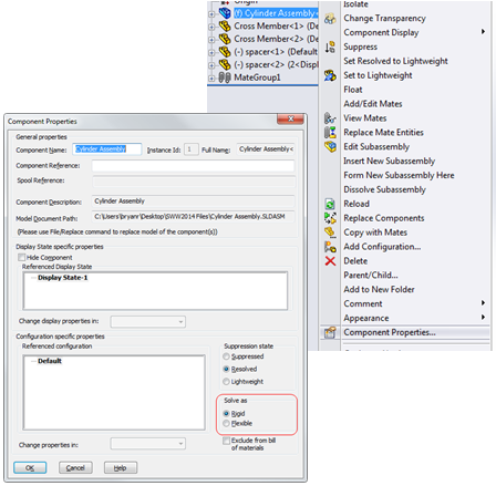 If we right click on the Cylinder Assembly in the design tree, we can select Component Properties and open our Component Properties window. In the bottom right hand of this window, you will see a Solve as area. Change it from Solid to Flexible. Going back through this, I also noticed that SOLIDWORKS loaded this as lightweight in my session. It will need to be resolved before you can select flexible. Doing this will allow the sub assembly to use the mates in the sub assembly to solve for location of the piston inside the cylinder.
Now if we look again at our main assembly, you can see that we can grab one of the cross members and move it around and it will actuate the cylinder. Granted, you could do the same thing if you put the components into the main assembly individually, but what if you purchased this cylinder and the supplier gave you an assembly model?
 Next, let's look at collision detection. Say we want to know how far the cross members will actuate when the cylinder is fully retracted. Select the Move Component function from the Assembly tab, in the Move Component window, select Collision Detection, These components, then click on the piston and cylinder. Click Resume Drag and then grab the cross member in the model and drag it. You'll notice when the cylinder is fully extended, the cross members just sweep by each other and flip to the bottom of the assembly, but when you drag it up, it stops. If you have the transparency turned down on the piston and cylinder, you can see that the piston bottoms out in the cylinder and the assembly stops. If we leave it at the stopping point, what is the angle between the two cross members?
Next time we will look at interference detection. As always, if you have any questions, please ask in the comments section.
Enjoy,
Bryan
Tuesday, August 18, 2015
CSWP Segment 3: Origins and Coordinate Systems
Segment 3 is about assemblies. It becomes nearly impossible to judge if your assembly is correct based on mass. Therefor we switch to reporting the Center of Mass or Center of Gravity. Because of this, we have to pay very close attention to the polarity of our answers. A negative sign can mean the difference between right and wrong here...
For example, the question in the box below can be answered without opening SOLIDWORKS.


For example, the question in the box below can be answered without opening SOLIDWORKS.

You can see that Z and Y must be positive and X must be negative. If Z is positive, then this eliminates the top two answers. If X must be negative, this eliminates the bottom left answer, leaving us with only one option, the bottom right.
So, it is important that you create and assemble your models with the origin in mind. If for some reason, you find yourself 3 questions deep and realize your coordinate system is wrong, there is a simple fix. We can use a Reference Coordinate System. Click Insert, Reference Geometry, Coordinate system to open the feature.

Select Edges to make the Reference Coordinate System match the test.

Hit the check box and you have a secondary Reference System. When computing the Center of Mass, make sure you have the new coordinate system selected in the window shown here.

On the next post, we will talk about how to insert a sub assembly and make it flexible.
Have Fun,
Bryan
Wednesday, August 12, 2015
Questions
I'm getting some questions through twitter about specific items. If you have a question, please reply to this post and I'll do my best to answer them.
Bryan
Bryan
Monday, August 10, 2015
CSWP Segment 2: Design Intent
I'm going to finish off Segment 2 on this post. Let's download and open this file: Shelled Part - Design Intent. It is a model of a wrench for a hex nut. I believe this section of the test explores your ability to understand design intent. There are several questions in this section of the test where you will have to understand how a model is created and to find the best way to update it based on the design intent.
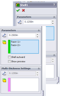 We start off with a question that asks you to change the wall thickness of this part. I want to touch on this briefly. I have a lot of questions in my classes about shells. In the CSWA exam, there is a question that leads the test taker down this path only to be faced with some serious issues when using it.
If we want to update the wall thickness, we would need to edit the shell feature and change the value from .125 to .250. As easy as that sounds,
Once the wall thickness is updated, determine the mass of the part.

Now, to focus in on the design intent portion. If we take the part we downloaded above, we can see the part and sketch that we start off with looks something like this:


Let's take the above and make a change to the base feature profile so that it looks like this:


I hope this helps everyone on Segment 2. I've got some special requests for Segment 3. I'll be posting some stuff on that soon.
Enjoy!!
Bryan
 We start off with a question that asks you to change the wall thickness of this part. I want to touch on this briefly. I have a lot of questions in my classes about shells. In the CSWA exam, there is a question that leads the test taker down this path only to be faced with some serious issues when using it.
If we want to update the wall thickness, we would need to edit the shell feature and change the value from .125 to .250. As easy as that sounds,
Once the wall thickness is updated, determine the mass of the part.
Now, to focus in on the design intent portion. If we take the part we downloaded above, we can see the part and sketch that we start off with looks something like this:


Let's take the above and make a change to the base feature profile so that it looks like this:

You can see that once we rebuild, the part looks like something that we would consider a good part, meaning that there is nothing that indicates a problem.

Let's revert back to the original downloaded state and extrude a cut on the front surface through the entire model.

When we rebuild the part, we see that we have a problem... That cut extrude broke out on the bottom of the handle.

The reason is directly related to the design intent or the way the model was built. We have a base shape, then we immediately move into a shell feature. Now if we cut extrude this feature through all, we see that the shell does not perform like it should. This is due to the shell command offsets from the outer surfaces to create the shell feature. We do in fact want the handle to be tapered on 3 sides, but we do not want the shell to break out of underside of the handle.
There is a very simple fix to this to follow the original design intent. As you can see in our design tree, our sketch and cut extrude are at the bottom of the tree. So we built our base feature, then shelled out based on that shape.
The correction is to drag the new feature to a location above the shell. When we do that, we can see that the shell now follows the new surface in addition to the previous surfaces.


I hope this helps everyone on Segment 2. I've got some special requests for Segment 3. I'll be posting some stuff on that soon.
Enjoy!!
Bryan
Tuesday, August 4, 2015
CSWP Segment 2: Design Tables
Design tables can sometimes be confusing. I've seen very simple design tables and I once saw someone use a design table and Excel's Goal Seek function to determine the level of water in a tank of a specific weight and update the model to the correct volume of water. As it relates to the CSWP exam, we need to learn how to create a table and use it to control some basic dimensions.
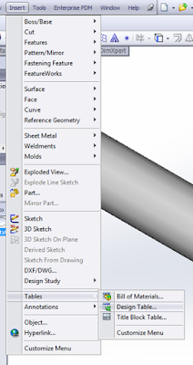 Once again, let's start with downloading the 2014 Version File that we have used on the last to blog entries. With the model opened, we can click Insert, Tables, Design Tables (see left) and open the dialog box shown to the right.
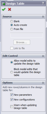
We are going to select the Auto-create button under Source. This will read our model and find any differences and populate them in the design table. Edit Control dictates whether your model will control your design table or if your design table will control you model. This can be set based on your needs. We will use the first option. The options section tells SOLIDWORKS what to consider a Design Table entry. We will select the first two. Once we have all our selections made, we click the check mark. Your interface will bounce around a bit and you will be presented with an Excel sheet in your Graphics User Interface that contains all the current configurations and it will also review the model and list all dimensions or states that are different. You can see below that the model is populated with the 5 configurations that we have used in the last two posts, it has populated the various lengths of the file and we see there are a sketch and a feature that have different suppression states.
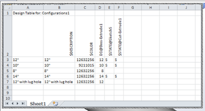
The design table operates using Excel. Any formulas of features you use in Excel are usable here. We need to make a new configuration, so, let's copy the entire row labeled in Column A as 10" and paste it into the next empty row. If you leave a blank row or column, SOLIDWORKS will recognize this and consider it the end of your design, so make sure there are no blank rows or columns.
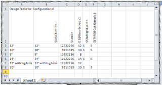
We don't need two configurations named 10", so let's rename Column A and B to 16". We will then go into Column D and change the value to 16. This represents how long the cylinder is.
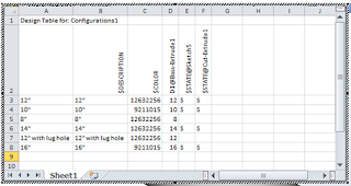
In order to exit the Design Table, you just need to click outside the design table in the GUI. Trust me, when working with Design Tables, you will do this on accident multiple times. :-P (see below on how to get back into the Design Table)
It will do some more bouncing and throw you a dialog box similar to this:

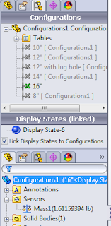 When you select OK, your configurations manager will give you a new symbol next to your configurations. It is the symbol for Excel which indicates that the configuration is controlled by the design table. To edit the configuration, you have to enter the design table. In order to do this, you need to click the plus sign on the Tables folder, right click the design table and select edit table.
Quick Check and the question everyone is asking... What's the mass?
Outside the Exam, Design Tables are a very powerful feature. We use them in my daytime job to control our customer models. The customer fills in some drop down boxes on our website, this gets shoved into the design table and out pops the model the customer needs.
Enjoy,
Bryan
 Once again, let's start with downloading the 2014 Version File that we have used on the last to blog entries. With the model opened, we can click Insert, Tables, Design Tables (see left) and open the dialog box shown to the right.
We are going to select the Auto-create button under Source. This will read our model and find any differences and populate them in the design table. Edit Control dictates whether your model will control your design table or if your design table will control you model. This can be set based on your needs. We will use the first option. The options section tells SOLIDWORKS what to consider a Design Table entry. We will select the first two. Once we have all our selections made, we click the check mark. Your interface will bounce around a bit and you will be presented with an Excel sheet in your Graphics User Interface that contains all the current configurations and it will also review the model and list all dimensions or states that are different. You can see below that the model is populated with the 5 configurations that we have used in the last two posts, it has populated the various lengths of the file and we see there are a sketch and a feature that have different suppression states.

The design table operates using Excel. Any formulas of features you use in Excel are usable here. We need to make a new configuration, so, let's copy the entire row labeled in Column A as 10" and paste it into the next empty row. If you leave a blank row or column, SOLIDWORKS will recognize this and consider it the end of your design, so make sure there are no blank rows or columns.

We don't need two configurations named 10", so let's rename Column A and B to 16". We will then go into Column D and change the value to 16. This represents how long the cylinder is.

In order to exit the Design Table, you just need to click outside the design table in the GUI. Trust me, when working with Design Tables, you will do this on accident multiple times. :-P (see below on how to get back into the Design Table)
It will do some more bouncing and throw you a dialog box similar to this:

 When you select OK, your configurations manager will give you a new symbol next to your configurations. It is the symbol for Excel which indicates that the configuration is controlled by the design table. To edit the configuration, you have to enter the design table. In order to do this, you need to click the plus sign on the Tables folder, right click the design table and select edit table.
Quick Check and the question everyone is asking... What's the mass?
Outside the Exam, Design Tables are a very powerful feature. We use them in my daytime job to control our customer models. The customer fills in some drop down boxes on our website, this gets shoved into the design table and out pops the model the customer needs.
Enjoy,
Bryan
CSWP Segment 1: Adding Material and Checking Mass
In Segment 1, it's all about mass. Every question asks you what the mass of the part is. In order to get the mass, we need to tell SOLIDWORKS what material we are working with.


Now, let's add a sensor.
Right click on the sensors folder and select Add Sensor

Under the Properties tab, select Mass and click the check box.
Expand the Sensors folder and you will see what the mass of the part is.

The sensor will update as you modify your part. I recommend using it as a general input to if you are going in the right direction. When it comes time to enter your answer, I highly recommend that you double click on the mass in order to open the Mass Properties window. You can set this to the number of decimals that the test requires answers to be given in. This eliminates one more chance for a mistake by rounding numbers in your head...

I hope this helps on segment 1. If you have any questions to anything I've posted on segment 1, please post them below.
Next time, we'll take a look at Segment 2.
Bryan
Let's back up to the model we created when we were talking about equations. Let's set A=30, B=10 and C will evaluate to 50.
The first thing we need to do is assign a material to the part.
Right click your part in the Design Tree
Select Material, then Edit Material

Select the material you have been asked to use from the list (1061 alloy in this case).
Click Apply, then Close.

Now, let's add a sensor.
Right click on the sensors folder and select Add Sensor

Expand the Sensors folder and you will see what the mass of the part is.

The sensor will update as you modify your part. I recommend using it as a general input to if you are going in the right direction. When it comes time to enter your answer, I highly recommend that you double click on the mass in order to open the Mass Properties window. You can set this to the number of decimals that the test requires answers to be given in. This eliminates one more chance for a mistake by rounding numbers in your head...

I hope this helps on segment 1. If you have any questions to anything I've posted on segment 1, please post them below.
Next time, we'll take a look at Segment 2.
Bryan
Monday, August 3, 2015
CSWP Segment 2: Adding Configurations
I'm going to break creating configurations up into two sections.
The first method is the simplest, but offers the least amount of options on the front side. In essence, you can only add a configuration and then name it. After you have done this, then you can modify it. Let's take a look at this method.
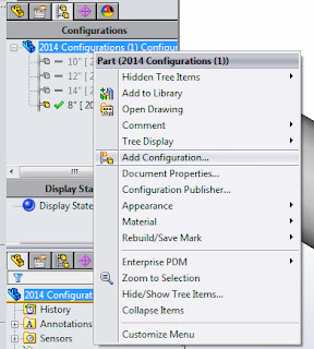 Let's use the same model from my last entry. Open 2014 Version File of the Cylinder. Open the configuration manager, right click on the parent part and select Add Configuration.
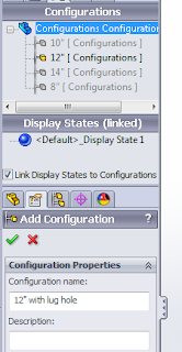
In the pop up window that we are given, enter 12" with lug hole in the configuration name and click the check mark. It's as easy as that. Now that you have a configuration, let's look at what we can do with it.
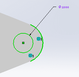
We have our new configuration and it is active, so let's make it distinguishable from the other configurations. We are going to add a lug hole to the cylinder. Sketch a .2500 diameter hole on the mounting lug as shown here and extrude cut it through all.
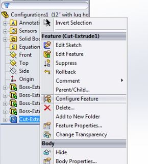
Let's take a look at the configure feature function. Right click on the cut extrude feature we just created and select 'Configure Feature'
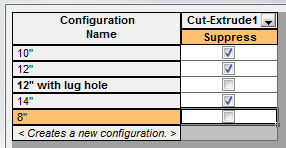
Let's suppress this new feature in the 10", 12" and 14" configurations.

The next entry will be doing the same thing with a Design Table. It gives a little more flexibility on the front side than the 'Add Configuration' method above.
Bryan
The first method is the simplest, but offers the least amount of options on the front side. In essence, you can only add a configuration and then name it. After you have done this, then you can modify it. Let's take a look at this method.
 Let's use the same model from my last entry. Open 2014 Version File of the Cylinder. Open the configuration manager, right click on the parent part and select Add Configuration.
 In the pop up window that we are given, enter 12" with lug hole in the configuration name and click the check mark. It's as easy as that. Now that you have a configuration, let's look at what we can do with it.

We have our new configuration and it is active, so let's make it distinguishable from the other configurations. We are going to add a lug hole to the cylinder. Sketch a .2500 diameter hole on the mounting lug as shown here and extrude cut it through all.
Let's take a look at the configure feature function. Right click on the cut extrude feature we just created and select 'Configure Feature'

Let's suppress this new feature in the 10", 12" and 14" configurations.
Now, if we switch to the 8" configuration, we see our lug hole, but if we switch to the 14", the lug hole is not turned on. And the question you most love to see, is what is the mass of the 8" configuration?

The next entry will be doing the same thing with a Design Table. It gives a little more flexibility on the front side than the 'Add Configuration' method above.
Bryan
Friday, July 24, 2015
CSWP Segment 2 - Configurations
This entry we are going to discuss configurations. Some people deal with configurations all the time, while others have never dealt with them. Segment 2 deals heavily with controlling configurations. We will look at two items that might be of interest on an exam.
First, let's start with downloading and opening a SOLIDWORKS file. It is a 2014 Version so you will be able to open it in 2014, 2015 or beta 2016.
The first thing you are going to want to know is how many configurations there are.
 Let's switch to the configurations tree by clicking the configurations tab and counting how many different configurations there are.
As you can see, there are 4 configurations. The configuration that is active is the 8" configuration. You can tell this because it is not grayed out.
Let's switch to the 12" configuration by double clicking on it.
 You can now see that the 12" is now colored and the 8" has been grayed out. The check mark signifies that the configuration has been through a 'resolved or rebuild' function.
The last question for this post is, what is the mass of the 12" configuration?

First, let's start with downloading and opening a SOLIDWORKS file. It is a 2014 Version so you will be able to open it in 2014, 2015 or beta 2016.
The first thing you are going to want to know is how many configurations there are.
 Let's switch to the configurations tree by clicking the configurations tab and counting how many different configurations there are.
As you can see, there are 4 configurations. The configuration that is active is the 8" configuration. You can tell this because it is not grayed out.
Let's switch to the 12" configuration by double clicking on it.
 You can now see that the 12" is now colored and the 8" has been grayed out. The check mark signifies that the configuration has been through a 'resolved or rebuild' function.
The last question for this post is, what is the mass of the 12" configuration?

0.1570 pounds is the answer.
Next time, we will continue on with adding configurations using 'add configuration' and a design table.
Bryan
Tuesday, June 30, 2015
Reading Chamfers
I've got a short post today. We need to talk about chamfers and how the test shows them. We all know that there are multiple ways to dimension a chamfer on a drawing. The exam uses a couple of different ways.
Here are a few ways you will see chamfers on the exam.


Here are a few ways you will see chamfers on the exam.

The key to chamfers on the exam is to know where the reference plane is. If you are shown a 45° chamfer, the orientation does not matter, but when you are given a 60°, the reference surface becomes very important. Here is an example for defining an edge chamfer.

Also, one word of caution, I've had several instances, more in the past, where chamfers flip on you in patterns or mirrors. Be wary of the chamfer...
Until next time,
Bryan
Monday, June 15, 2015
CSWP Segment 1: Equations
In this entry, we’ll discuss equations and variables. By using variables, you can assign a
dimension to multiple features or sketches and update them from one
location. This is much easier than
trying to remember in your model where the dimension 15mm occurs. Also, an equation in SOLIDWORKS is a very
powerful tool. You can control parts and
have them automatically update in regards to new dimensions or updated
dimensions in a design.
Segment 1 uses variables and equations throughout the
test. Before we begin the exam, let’s
turn on two features in SW that will come in handy. If we go to Tools/Options – System Options
then Feature Manager, we can set Equations and Sensors to ‘Show’. This will populate both in the design tree so
we can easily find it when we are working on our test. We will discuss Sensors later in the blog.

Now when we start a new part, in the feature tree, we can
see both of these options.

When we start our test, we see that we are given some variables and further into the test, we are given an equation. Let’s look at how to enter these variables and equations before we even start modeling.
We will start a new part, right click on the equations
folder and select ‘Manage Equations’. This
will open up our equations dialog box.
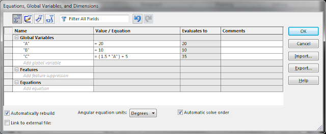
Under Global Variables, type the letter A. Tab over to Value/Equation
and give it a value of 20. Hit the Enter
Key and it takes you to the comments box.
In a real world application, you can give this variable a description so
that people after you know what it is.
For the purpose of the test, there isn’t much value in this field. If you hit Enter again, it drops you to a new
line under “A”. Now set B equal to 10
and start a third line. On the third
line, we are going to set C equal to the equation (1.5*’A’)+5. You will notice at the bottom of the equation
manager that there is an equation section.
This is for a direct application of an equation to a dimension. While it is not needed for the exam, you can
double click a dimension and apply an equation to it from directly in the
model. The equation will be displayed
here. Let’s also check the ‘Automatically
Rebuild” box. We can now click OK and
close out the equation manager dialog box.
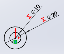
Let’s start our part on the top plane. Select this plane and start a sketch. On this plane, we will sketch two circles with the center on the origin, one slightly bigger than the other. Put a dimension on both, the value does not matter at this point.

Let’s start our part on the top plane. Select this plane and start a sketch. On this plane, we will sketch two circles with the center on the origin, one slightly bigger than the other. Put a dimension on both, the value does not matter at this point.

Double click the dimension for the inner circle (32.27 above). If we type =A in the dimension, we can now link this dimension to the variable A.

Click the check and repeat the process for the second dimension, linking it to B.
You will see that we now have our diameters linked to our
variables and SOLIDWORKS is show us a new symbol (Red Sigma) that means we are
linked to the equations manager.
Now, let’s extrude this part. Select the Features tab, click Extrude Boss/Base and in the Direction one boss, set D1 equal to C. Click the check mark and we have a part!
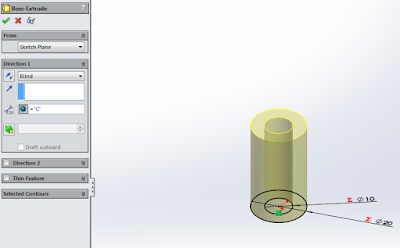
Now, let’s extrude this part. Select the Features tab, click Extrude Boss/Base and in the Direction one boss, set D1 equal to C. Click the check mark and we have a part!

Why is this important? On the exam, the variable will change. The variables are also used multiple times in the exam. This is done to force you to show your knowledge of how to use them. It’s much easier to change A in the Equation Manager rather than sift through your models and find every instance of A.
If we open the equations manager again by right
clicking on equations and selecting manage equations we can change these
variables. Let’s change A from 20 to
30. Move the equations manager off the
model so you can see what happens when you click ok.
Our part changed from this:
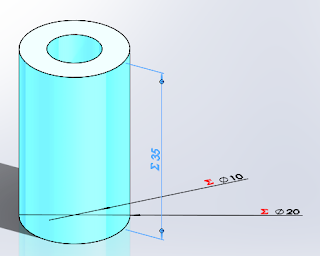

To This:

Diameter A updated from 20 to 30 and Length C updated to from 30 to 50.

Diameter A updated from 20 to 30 and Length C updated to from 30 to 50.
If you have any questions on equations, post them below and
we will discuss them.
Next time we’ll talk about materials and mass.
Bryan
Subscribe to:
Posts (Atom)