
The first method is the simplest, but offers the least amount of options on the front side. In essence, you can only add a configuration and then name it. After you have done this, then you can modify it. Let's take a look at this method.
 Let's use the same model from my last entry. Open 2014 Version File of the Cylinder. Open the configuration manager, right click on the parent part and select Add Configuration.
 In the pop up window that we are given, enter 12" with lug hole in the configuration name and click the check mark. It's as easy as that. Now that you have a configuration, let's look at what we can do with it.

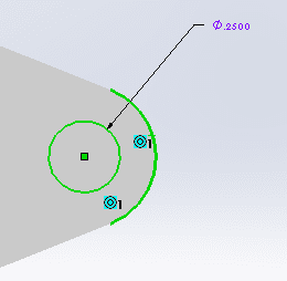
We have our new configuration and it is active, so let's make it distinguishable from the other configurations. We are going to add a lug hole to the cylinder. Sketch a .2500 diameter hole on the mounting lug as shown here and extrude cut it through all.
Let's take a look at the configure feature function. Right click on the cut extrude feature we just created and select 'Configure Feature'

Let's suppress this new feature in the 10", 12" and 14" configurations.
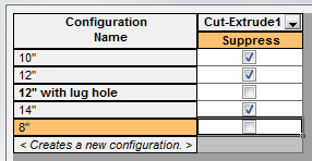
Now, if we switch to the 8" configuration, we see our lug hole, but if we switch to the 14", the lug hole is not turned on. And the question you most love to see, is what is the mass of the 8" configuration?

The next entry will be doing the same thing with a Design Table. It gives a little more flexibility on the front side than the 'Add Configuration' method above.
Bryan
No comments:
Post a Comment